
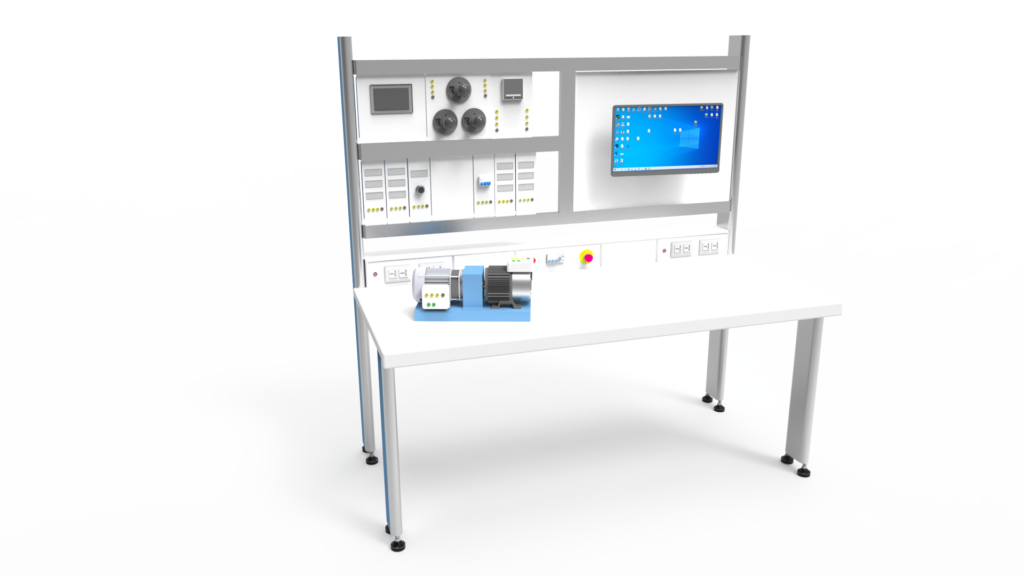
ชุดทดลองระบบเครื่องกำเนิดไฟฟ้าแบบซิงโครนัส
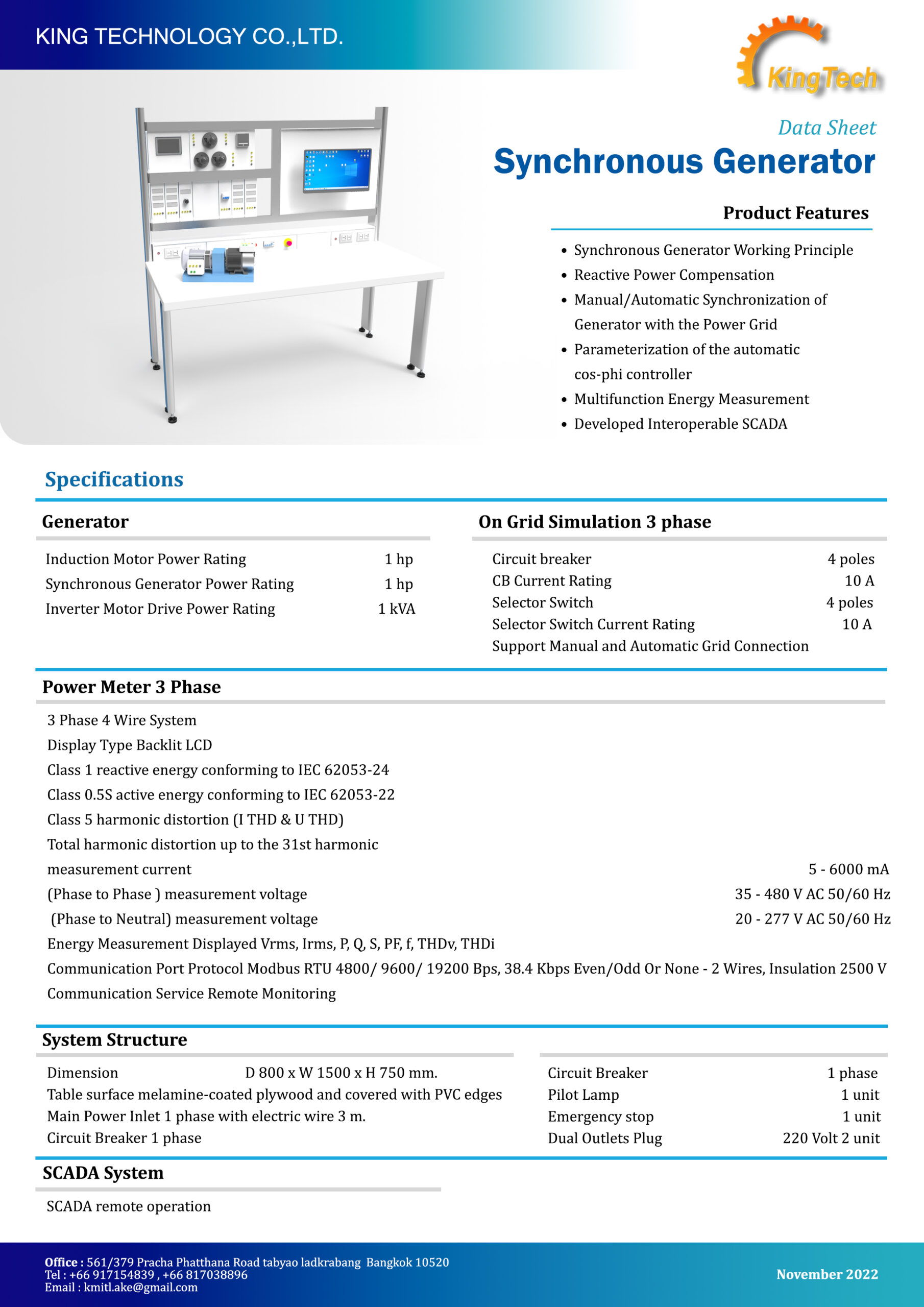
- Synchronous Generator Working Principle
- Reactive Power Compensation
- Manual/Automatic Synchronization of Generator with the Power Grid
- Parameterization of the automatic cos-phi controller
- Multifunction Energy Measurement
- Developed Interoperable SCADA
| Spectification | |
| Generator | |
| – Induction Motor Power Rating – Synchronous Generator Power Rating – Inverter Motor Drive Power Rating | 1 hp 1 hp 1 kVA |
| On Grid Simulation 3 phase | |
| – Circuit breaker – CB Current Rating – Selector Switch – Selector Switch Current Rating – Support Manual and Automatic Grid Connection | 4 poles 10 A 4 poles 10 A |
| System Structure | |
| – Dimension – Table surface melamine-coated plywood and covered with PVC edges – Main Power Inlet 1 phase with electric wire 3 m. – Circuit Breaker 1 phase – Pilot Lamp – Emergency stop – Dual Outlets Plug 220 Volt | D 800 x W 1500 x H 750 mm. 1 unit 1 unit 2 unit |
| Power Meter 3 Phase | |
| – 3 Phase 4 Wire System – measurement current – measurement voltage 35 – 480 V AC 50/60 Hz between phases – measurement voltage 20 – 277 V AC 50/60 Hz between phase and neutral – Energy Measurement Displayed Vrms, Irms, P, Q, S, PF, f, THDv, THDi – reactive energy conforming to IEC 62053-24 – active energy conforming to IEC 62053-22 – harmonic distortion (I THD & U THD) – Total harmonic distortion up to the 31st harmonic – Display Type Backlit LCD – Communication Port Protocol Modbus RTU At 4800 Bps, 9600 Bps, 19200 Bps, 38.4 Kbps Even/Odd Or None – 2 Wires, Insulation 2500 V – Communication Service Remote Monitoring | 5 – 6000 mA Class 1 Class 0.5S Class 5 |
| SCADA Management | |
| – SCADA remote operation |

